Edit Contact
Delete Contact

SatVector


Communication

Syncing data...

Rise Time (Local)Max ElevDurationVisibility
No predictions calculated.

Rotor Design & Customization

The SatVector control system can be used for nearly any rotor that is powered with an Arduino and uses stepper motors. However, the SatVector software was designed with the SatNOGS rotor in mind and will work out of the box, provided no modifications were made to the drive system. Visit the Software/Help section to see what minimal adjustments may be required for your own design or a drive-modified SatNOGS rotor.

If you choose to use the SatNOGS rotor design for your ground station, there are a few minor modifications you can make. Aluminum shafts specified in the SatNOGS BOM were replaced with 3D-printed ones, measured to precisely match the inner diameter (ID) of the 6008zz bearing, with a hollow core for pass-through of 3/4" PVC for antenna mounting.

Joining clips to connect the 2020 aluminum frames for the az and el modules were created by @dflemst.

All 3D-printed parts were made using PETG filament on an Bambu Labs A1 Mini. Additional .stl files for component mounting are provided at the SatVector Github.

Control System Hardware

The system is powered by an Arduino Nano ESP32, chosen for its built-in Bluetooth Low Energy capabilities, lower cost, and faster processing. Motion is driven by NEMA 17 stepper motors controlled via A4988 motor drivers, allowing for high precision on both azimuth and elevation axes.

Both Arduino Nano and A4988 drivers are mounted on solderless breakout boards for easy assembly, replacement, and wiring. The A4988 breakout board includes switches for micro-stepping, a capacitor to help buffer 12vdc motor power, and discrete logic & 3v-5.5v circuit power inputs.

To ensure field-readiness and minimize cable entanglement where possible, the unit is designed to run off a DeWalt form factor 20V battery mounted atop the rotor. However, any reliable 12VDC source providing at least 2A will work.

Component List (BOM)

All components used in the control system. Amazon links are affiliate-supported.

Arduino Nano ESP32
Integrated BLE with headers
NEMA 17 Stepper Motor
1.8° • 42mm • 12V
HiLetGo A4988 Motor Driver
Simple, low-cost motor driver for the NEMA 17
Motor Driver Expansion Board
Solderless breakout board for A4988 driver
HiLetGo Nano Expansion Board
Solderless terminal expansion board for Arduino Nano
ChoikWon Stepdown Transformer
20VDC to 12VDC step-down transformer for DeWalt batteries
LM2596 DC to DC Buck Converter
Converts 3.2V-35V to 1.25V-30V for A4988 motor driver circuits


Hardware Configuration

Minimal configuration of hardware is required. Ensure that all three microstepping switches on the stepper motor expansion board are set to 1/high so your motor microsteps at 1/16. This is required for the math set within the Arduino sketch to determine steps per revolution.


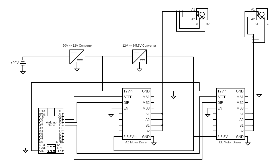
Wiring the Controller Hardware

Wiring together the various components for the rotor hardware is pretty straight forward, however there are a few important notes about the schematic.

Circuit Notes
This schematic is provided as-is with no guarantees. It's up to you to review the manufacturer documentation supplied with each part to ensure you are connecting these devices as directed.

The ChoikWon transformer, shown as the 12V -> 3-5.5V Converter, is an adjustable voltage device. Before connecting to the A4988 circuitry, use a voltmeter to ensure the output is adjusted correctly, between 3-5.5V.

Wiring from the motor drivers' output to their respective stepper motors in the diagram is consolidated to a single line for visual simplicity only. Do not solder these wires into a single connection to the motor.

The pin-outs shown for the A4988 are not a direct translation to their position on the breakout board or the A4988 circuit itself. The driver expansion board is labeled to help you connect wires correctly.

MS1, MS2, MS3 are for micro-stepping. The A4988 breakout board has a switch for each; set each of these to "on" for full microstepping. This is integral to the math coded into the sketch and also prevents floating ground causing spurrious motor movement.

Download Schematic from SatVector Github

SatVector Basic Operation

Unregistered Users

Choose your satellite: In the Tracking section, use the search function to find the desired satellite from the drop-down list of amateur radio and weather satellites.

Choosing Location: Non-registered users may select their current location by double-clicking on the map or manually entering lat/lon.

Pass Predictions: Click the Predict Selected (48hr) button in the Tracking section to get a list of upcoming passes for the next 48 hours. TLE data is refreshed nightly to stay current.

Maidenhead Grids: To see Maidenhead grid squares overlaid atop the map, click the Maidenhead Grid checkbox in the upper right of the map. Zoom in to see the full LLNN locator data.

Transmitter Data: Transmitter data for the selected satellite is displayed to the left of the map in the Tracking section.

Registered Users

Choose Favorite Satellites: In the Preferences section, use the search feature to find your favorite satellites. Click the check box next to the desired satellite to select it as a favorite. Now when using the Tracking section, only your chosen favorites will be listed for a cleaner experience.

Pass Predictions: In addition to the single satellite predections, you can click the "Predict Favorites (48hr)" to run predictions for all of your selected favorite satellites at once.

Set Location: In Preferences, you can add your location and set it as your active one so every time you load SatVector your data is accurate for your preferred location.

Registered users can use advanced features such as selecting favorite satellites, pass prediction for all favorites, rotor tracking, contact logging, and log exports. Registration is free and required for these features because they utilize user-specific preferences.

How the Tracking System Works

The SatVector website acts as the central brain of your ground station. It handles the heavy math by using current TLE (Two-Line Element) data to calculate exactly where a satellite is in relation to your location. Using a JavaScript library called satellite.js, the site performs these orbital calculations once every second.

When you connect SatVector to the rotor, the website begins a Bluetooth "handshake" with the Arduino Nano ESP32 inside your rotor to establish its connection. The website calculates the satellite position and transmits coordinates to the rotor. Instead of sending raw text, which is slow and prone to errors, the site sends a compact, 5-byte binary packet. This structured packet relays the target azimuth and elevation values in degrees to the Arduino, which calculates the steps each motor must move to meet those angles.

The packet structure is outlined in the table below. You will notice the azimuth and elevation values are multiplied by 10; this is done to avoid floating point numbers in the packet. The Arduino sketch divides the value by 10 to restore the original value when computing steps.

The Data Packet Structure:
[Byte 0]: Command Type (tells the Arduino to move)
[Byte 1-2]: Azimuth Target (Target angle multiplied by 10)
[Byte 3-4]: Elevation Target (Target angle multiplied by 10)

The Arduino iterates through the necessary steps/pulses, and after each step updates the website with the new position in degrees. This process repeats until the satellite position and rotor position match. The SatVector website updates satellite position every second.

Programming your Arduino

Download the sketch from the SatVector Github and open within the Arduino IDE. Connect your Arduino Nano ESP32 to your computer, choose the board & port within the IDE, then click the "Upload" button. When using the SatNOGS rotor and setting your A4988 microsteps as specified in the Hardware section, no code adjustments are necessary.

Software Adjustments

To adapt the control software for a non-SatNOGS stepper-powered rotor, there are a few important adjustments that should be made to the sketch.

Near line 27 is where the steps per rotor revolution is set. This value is critical to ensuring proper positioning regardless of your rotor design. The website sends positional changes in degrees to the Arduino controller where they are converted into steps. Look for the code snippet below to adjust steps per degree, based on your rotor's gearing. The default value for a SatNOGS rotor using a Nema 17 with full microstepping is 480 steps per degree, or 172,800 steps per rotor revolution.

Adjust steps per degree
const float STEPS_PER_DEG = 480.0;

In the Settings section of SatVector you can use directional buttons to move your rotor manually. Each click by default is configured to move your rotor by 0.5 degrees, or 240 steps. If you are using a rotor other than the SatNOGS design or simply want to adjust how far each manual jog adjusts the rotor look around line 251 and change the JOG_STEPS value. Note: If you change this value, the "0.5° deg/click" label above the manual adjustment buttons will not be relevant to your configuration.

Adjust steps per click - manual movement
const long JOG_STEPS = 240;

How to Track Using SatVector (Chrome/Edge only)

Power on your rotor. Navigate to the Preferences section and click the Connect button. Chrome will present a pop-up with the Arduino controller it's attempting to connect with. Choose the Arduino and click "Pair". If the website gets refreshed, you will need to reconnect your rotor. When successfully paired, a "Connected" message will post in the rotor console.

Once connected, the position values default to 0° azimuth and 0° elevation despite the physical position of the antenna. You must manually align the axes and zero/tare the value within SatVector. Use the directional controls within the Settings section to level your antenna to 0° of elevation. A small torpedo level or digital inclinometer is helpful here. Use a compass or a compass app on your smart phone to assist aligning your rotor with magnetic north. The magnetic declination calculator below can help you determine the necessary adjustment from magnetic north to true north based on your location.

When your rotor is aligned to true north aziumuth and 0° of elevation, click the "Set Current Position = 0°" button to zero out the system. Click the Track button to begin tracking the selected satellite when it comes in range. SatVector will automatically stage the azimuth at 2 minutes prior to the pass and begin full tracking once elevation is > 0°. Staging may not occur if a satellite is selected within 2 minutes of the pass or the pass is already in progress.

The rotor azimuth and elevation boxes will be outlined in green when tracking is active.

Magnetic Offset (WMMHR-2025)

What is SatVector?

SatVector started as a personal project to build a satellite tracking tool for macOS, but it has since grown into a web app for tracking, logging, and rotor control. The goal is to make amateur radio satellite tracking & communications approachable to seasoned operators and beginners alike. By providing a simple way to predict passes, log contacts, and control antenna hardware directly through the web, SatVector lowers the technical barriers to entry for a tech-forward and enjoyable facet of ham radio.

Why Register?

Registration is required to use rotor tracking and other functions because features such as logging, satellite preferences, and location information are user-specific. Registration and use of SatVector is free.

Privacy Statement

SatVector provides satellite tracking and pass predictions, along with the hardware and software informational resources to assemble a complete, user-friendly tracking station. All data you provide, including contact log data, stays within SatVector. SatVector does not sell, provide, or otherwise distribute any data you provide to any 3rd parties.

You may encounter Amazon affiliate links and/or ads on this site for related parts and hardware. These links and ads help pay for hosting and keep SatVector free.

New Log Entry

Recent Contacts
Date/Time Call Sign Satellite Mode Grid
Loading logs...

Locations & Station Info

ADD NEW LOCATION

Favorite Satellites

Select satellites to show in the tracking dropdown.

Rotor Control


AZ
EL

Rotor Data


AZ: 0° EL: 0


?: